CNC Milling Machine
The following project highlights my technical Solidworks skills of designing a unique desktop CNC milling machine (Figure 1). This was a team based project that included four individuals and was for our second year mechanical design course. CNC stands for Computer Numerical Control which means that instead of operating a mill manually, the computer does it instead. G-code (programming language) is used within the CNC mill which allows it to control the components, such as the spindle. The benefit of using a CNC mill is that it produces incredibly precise results when cutting and drilling into materials, therefore eliminating human error.
Through research and multiple team brainstorming sessions, candidate designs were formed. These designs were derived from primarily varying three components; the number of axes, the number of rotational and linear axes, and to which components the motion would be applied. Additionally, the size chosen for the CNC was 20"x20"x20"; this gave us a compact shape for a desktop machine and allowed for free motion in all three axes by the drill bit and spindle.
Our CNC milling machine was a 5-axis machine. It consisted of translation in the x-y-z axes in addition to rotation about 2 separate axes. Translation was done by the drill and rotation by the rotating bed. The bed rotated about the A-axis (Figure 2) while the rotating plate (located on top of the bed) rotated about the C-axis (rotates about itself).
The bed was able to support a relatively heavy load. In order for it to function it required a torque multiplier as the stepper motor selected wasn't sufficient enough, thus, a 1:30 speed reduction worm gear was used to achieve the required torque. Similarly, the plate was also able to support a relatively heavy load and required a 1:30 speed reduction worm gear to achieve the required torque (Figure 3).
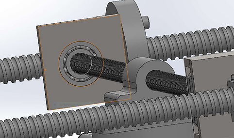
In terms of the translational mechanisms, the translation in the x-axis was conducted by a set of two ball screws (Figure 4). A rectangular face on the ball nut was chosen so that it could be integrated with the supports that were connected to another lead screw that governed the translation in the y-axis. Lead screws were used for the y-axis translation as they allowed for smaller and precise machining by the drill bit (Figure 5). Finally, for translation in the z-axis, we used two ball screws that allow the x- and y-axes translation mechanisms and the drill bit to move vertically (Figure 6). The thickness of the ball screw was increased as it had to support the weight of the motor, drill bit and remaining lead/ball screws.

Figure 1. Assembled desktop CNC milling machine

Figure 2. Rotating bed about the A-axis

Figure 3. Worm gear

Figure 4. Translation in the x-axis

